2859
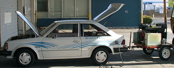
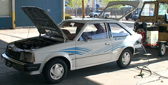
1981 Jet Electrica with Generator
Trailer
4/26/09 |
PURPOSE:
- a hands-on hybrid EV test bed
- direct operating experience the
primary goal
- minimum $ cost
- quick results (no component development)
- not a permanent vehicle
- not optimized for anyting
- basis for future permanent vehicle projects
FEATURES:
- original GE?
motor an 4 speed manual transmission
- battery pack of
10 Costco Deep Cycle Marine 12 volts
- auxilary battery same as traction
batteries
- battery pack chager manual variac
to bridge rectifier 115 VAC
- auxillary charger is a 3 amp
laptop AC adapter on main pack
- 15KW gasoline air cooled generator
- 240 to 120 volt transformer to
get to battery pack voltage
|
CONDITION:
1981 vintage
basically original Jet Electrica with minor modifications.
Exterior dents, wrinkles and dings. Original paint and
interior.
Seats and exposed surfaces show the age. Battery
boxes seriously corroded. Original tires? ~15,000
original miles? About 5,000 miles since brought back to life
in 2007.
SURPRISES:
1) Batteries don't like to absorb the capacity of the genset
1.5) Batteries have high resistance--voltage really drops to get rated current.
2) It takes about 50% more energy for ~50% increase in load
3) Road bounce floods a float carb on a genset.
THINGS TO DO:
1) Add low side AC voltage and current meters
2) Check battery discharge voltage curves with independent meters
3) Characterize trnasformer input voltage versus idle current
4) Find better batteries
5) install connectors for data & control lines so trialer can be disconnected
6) Obtain fuel burn versus KWH data
7) Install a computer type data collecting system
8) Make a force versus speed curve for the car (and same for trailer)
9) Find a way to eliminate the transformer
10) Get scope images of various point in they system
11) Do some calibration of the instrumentation
12) Generate wiring diagrams
|
This
is an experimental test-bed setup for obtaining some real world data.
I would discourage anyone from trying the same thing at this
point. Intial performance data looks mixed.
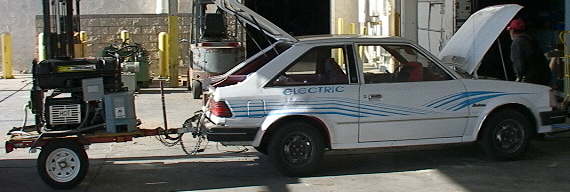
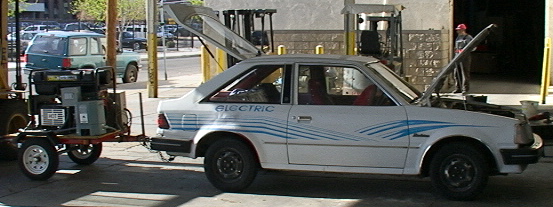
I
am currently running this as an electric traction only plug-in hybrid.
What that means is I charge from the wall then drive until
the
weakest battery gets to a resting voltage just above 10.5 volts.
This gets me about half to 2/3rds of one leg of my daily
commute.
Then I fire up the generator. I will idle or turn off the
generator if we get stuck in stop and go traffic or turn it on if going
up hill or needing more acceleration or speed. The commute is
about 35 miles round trip each day.
We have gone about 500 miles todate with this configuration. We currently run a driver and 2
passengers. Speeds range between 30 and 50 (except where
limited
by traffic). Current average KWH per mile is .42 (wall and genset power combined).
The generator puts out nominally 240 volts.
In order to match the 120 volt battery pack, we are running
through a 15KVA transformer and then a rectifier and then parallel with
the controller across the battery pack. We can start and stop
the
generator while driving, as well as disconnect it electrically which
drops it into an idle mode (when no current is drawn). (We
don't
have a remote choke so we need to start it to warm it up a bit when
cold.) We intercepted the voltage regulator loop of the generator and
feed it through a small variac on the dash to give us some control over
the generator output voltage (the original idea was we would need this
to prevent stalling the generator under heavy acceleration--but this
has not been needed to date).
It looks like it takes 50% more energy
to move the arrangement down the road at the same speed as it did with
just the car. Having added only two small wells and less than
50%
more weight, it seems about right except that the running currents are about twice what they were
(70 to 80 amps at 35 mph now versus 35 to 40 before).
At
such slow speed, wind resistance should not be an issue. Only
other thing I can think of right now would be trailer wheel
alignment--tires are not obiously scuffing--will have to try to figure
out a way to check that. Having refilled just once,
it looks
like the generator gets terrible gas mileage. Even though it
is
providing just a third of the KWh used, and is running less than
half the time, it is burning about a gallon every 20 miles.
(Obviously, more data needs to be gathered and the
calculations
reviewed.)
The obvious problem at this point is the battery
pack. The 10 12-volt 115 amp-hour marine deep-cycle and
starting
batteries can dish out a fair amount of current (albeit with
considerable voltage drop) but they simply don't want to charge any
faster than about 30 amps. I have about 120 amps continous
available from the generator but when I let go of the throttle coasting
to a stop or when stopped, the batteries only draw about 30 amps.
While the generator governor does back the engine off, I am
still
wasting the potential of 90 amps of recharging. On
accelerating
away from a stop, I can see peak current draw from the generator reach
140 amps (about 77 amps on the 220 volt side--so I am loosing some in
the transformer). (At sea level, I should be able to see a
peak
current of about 90 amps but at 5000 feet, the engine just does not
have that much power).
The
trailer and genset add about 50% more tire and weight. The generator
wet weighs about 500 pounds and is supposed to be about 30 hp.
The transformer is about 200 pounds. The trailer
and deck
is about 300 pounds. Additional electricals are about 100
pounds.
The 15 KW generator size was picked as it would have provided
about the right continous power for traveling 60 to 65 miles per hour
with the current draw of the car without the trailer. The
reason
for the unexpected current draw with the trailer is not yet determined.
The current suspect is toe-in of the trailer alignment.
The
exhaust of the genset was getting everything around it very black
indicating serious over fueling or rich mixture. We took it
to a
small engine shop where it was determined that it was just fine sitting
still. However, if you jostled the trailer
simulating what
happens driving down the road (even though it does have springs), the
engine would over-fuel badly from gasoline sloshing out of the
carberator and into the intake manifold. The current
attempted
solution is to reset the float level as low as possible without
starving it. This is facilitated by having positive pressure
fuel
delivery. It suggests that going to throttle body fuel
injection
might be desireable.
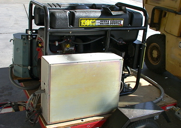
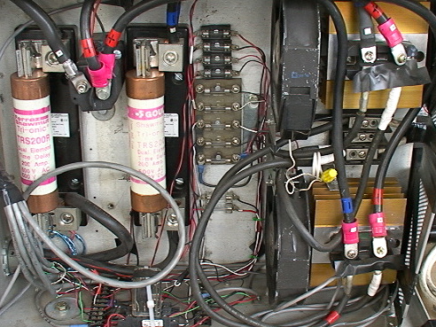
The image below is of the contents of the metal box above. On
the right are a pair of bridge rectifiers on heatsinks with fans to the
left of the heatsinks. These retifiers are currently hooked
in parallel. The Fuji rectifiers are rated 800 volts 100 amps
each.
In the center are buss fuses for the signal wires. both sides
of signal lines are generally fused this was.
Two the left are a pair of 200 amp fuses. Between the fuses
is the DC contactor that is remotely switched in an out to connect the
genset to the battery pack in the car.

The image above shows the label on one of the bridge rectifiers.
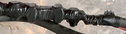
The image below is the taped up current shunt on the DC lead to the
battery pack that gives the DC current from the genset.
There are 4 basic operating modes:
1) driving on battery only.
2) accelerating with genset running--all genset power including surge
capability going to the motor and supplemental power as needed coming
from the battery. The acceleration period where genset surge
capability is used is very short--a minute or less. Other
high current demand--climbing a hill--needs to be limited to continuous
power rating.
3) running with genset on such that genset is supplying running power
and excess continuos rating power is recharging the battery pack.
4) genset still running when motor demand is zero (coasting and
stopped)--maximum continous genset power going into recharging
batteries until an "on the road" full charge state (50%?) is reached at
which point the generator is shut down.*
* With the current air-cooled genset, I want to allow a couple minutes
of idle cool down before actually turning the genset off based on past
experience with air cooled aircraft engines and old VW bugs.
This should not be as necessary on a liquid cooled engine (depending on
the coolant system design).
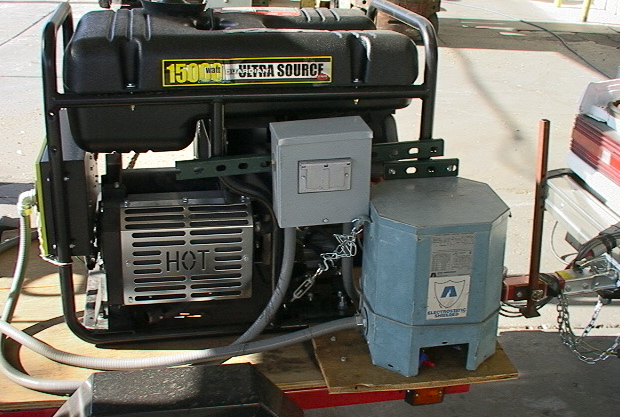
The metal box above houses the ac to dc rectifier, power contactor and
current shunt for the generator.
The
blue octagon in the image below is the 15 KVA single phase 240 to 120
volt transformer. The gray box slightly above and to the left
houses the generator digital KWH meter.
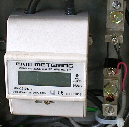
Below is the EKM KWH meter that keep track of the energy taken out of
the genset. It is on the 240 volt side so its 100 Amp
capacity is more than adequate. It is in the gray electrical
box with the weather cover window. To the right in the box is
the 240 volt AC current shunt.
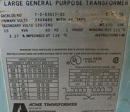
The image above is the placard of the transformer.
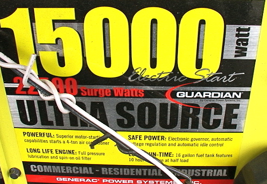
The images above are the genset labels.
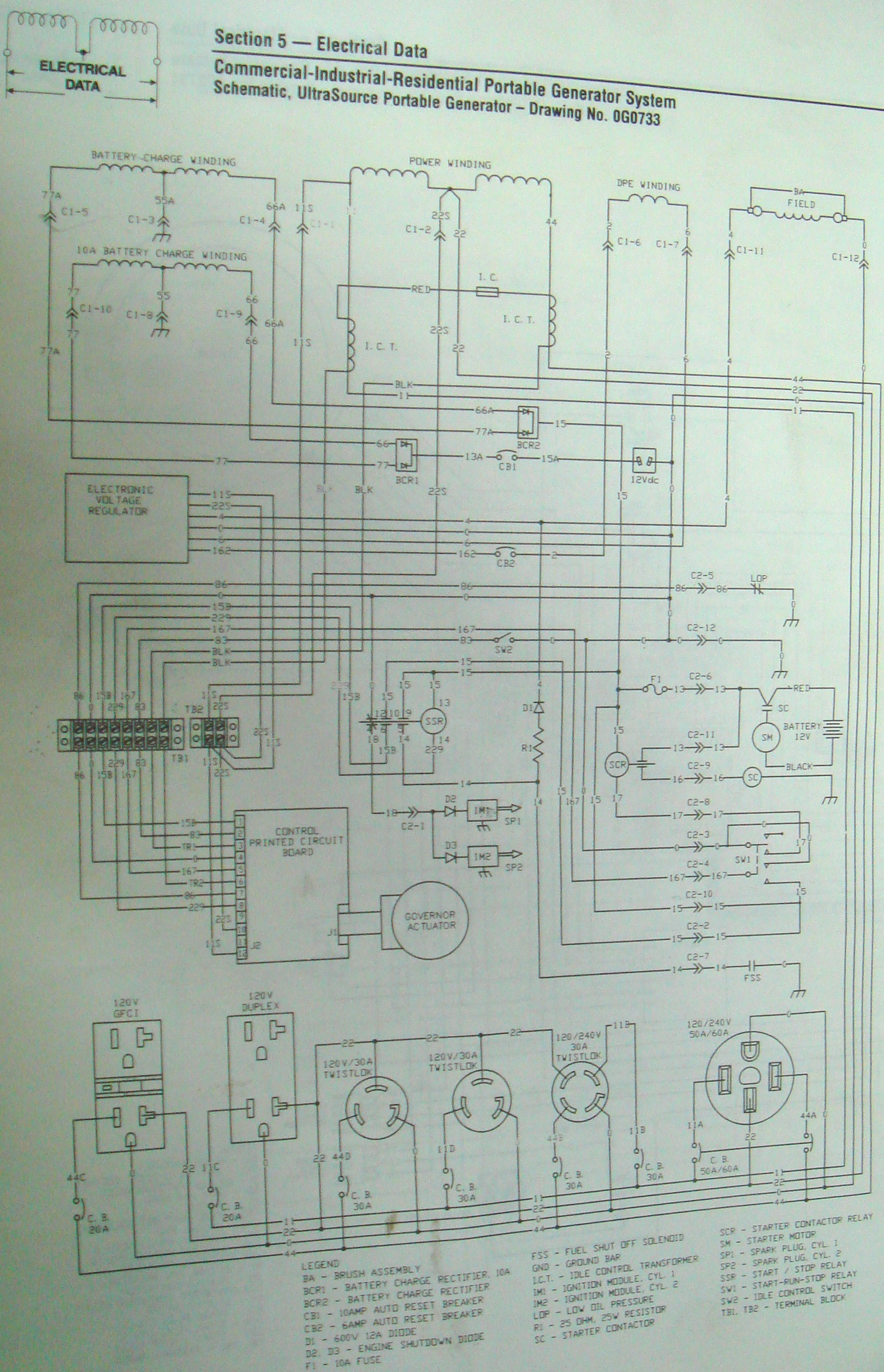
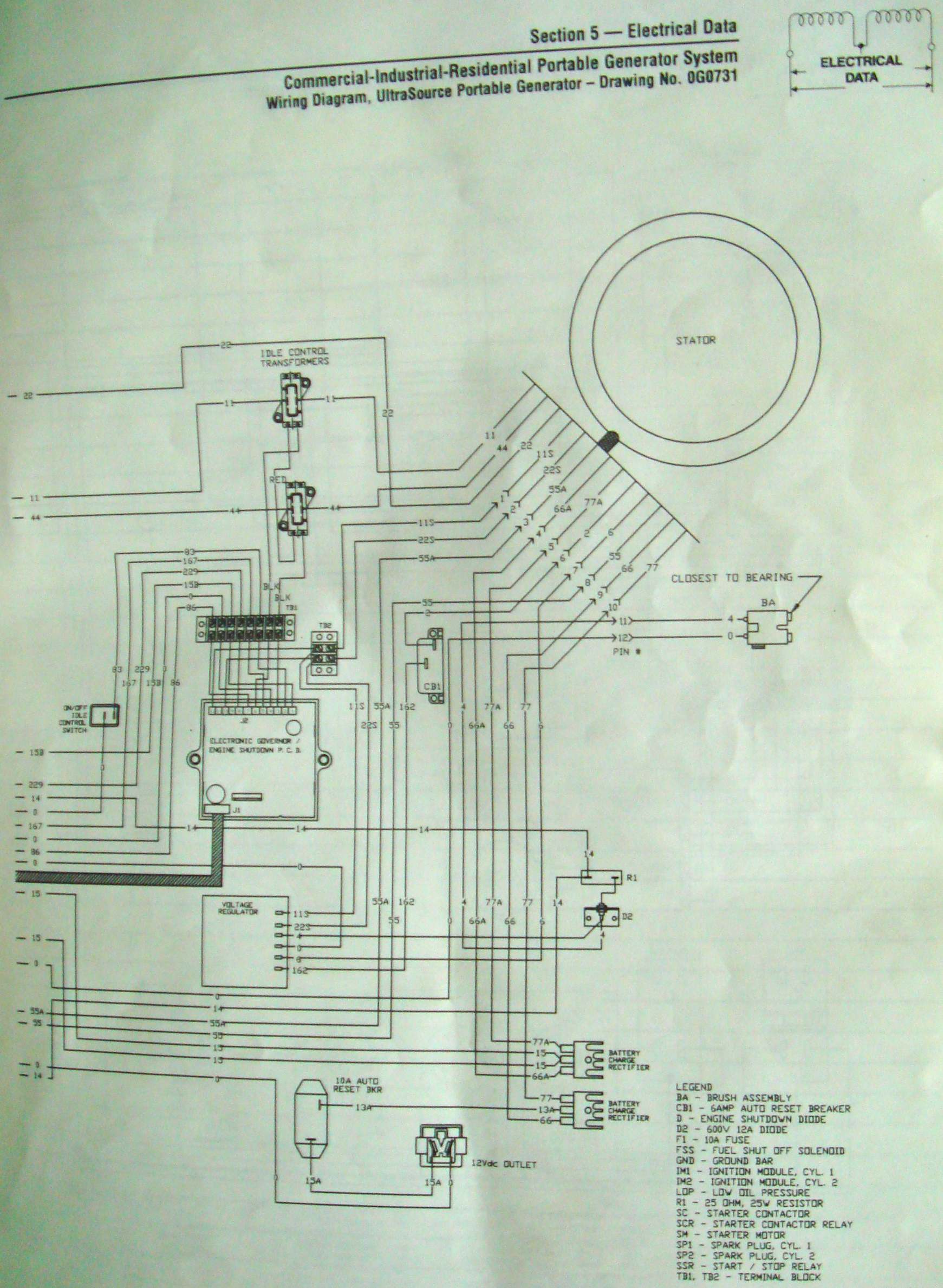
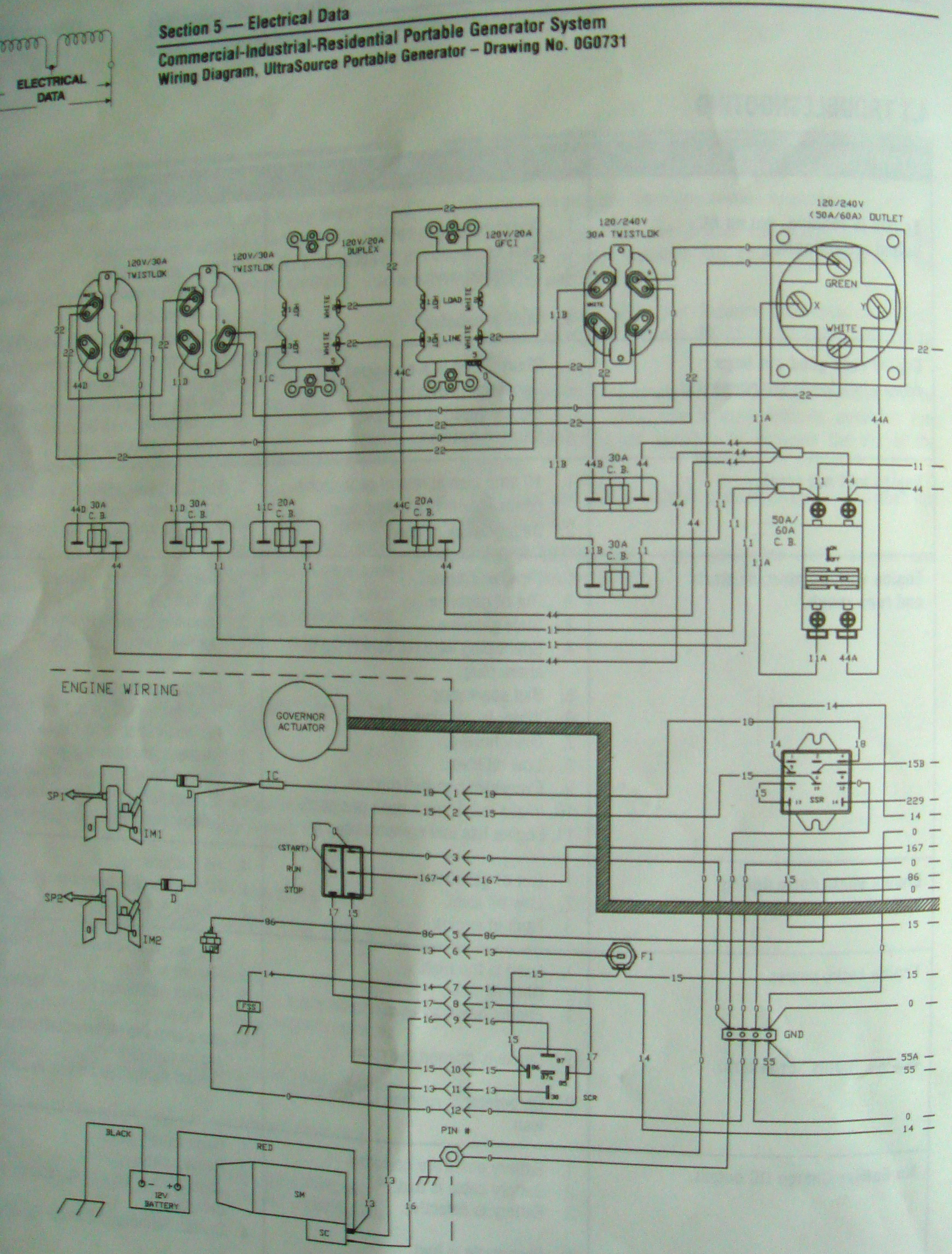
The images below are diagrams and and specs from the genset manual.
It looks like it might be possible to change to 120 rather
than 240 volt output if the ends of the power windings can be accessed inside the gnerator case.
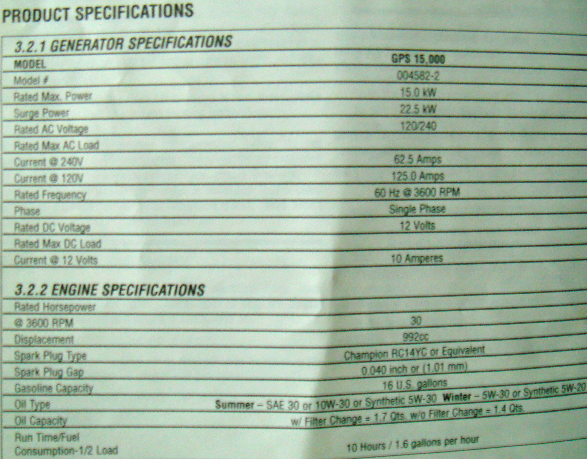
The spec. says 1.6 gallons per hour at half load. Currently,
I think we average about half load when the genset is running.
We have it running about 15 minutes of each 18 mile trip.
That implies we are using .4 gallons per 18 mile trip or a
gallon per 45 miles. I don't think we are getting near that
good. Plus, this represents only about 2 of the 8 KWH
consumed per 18 mile trip.
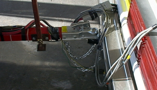
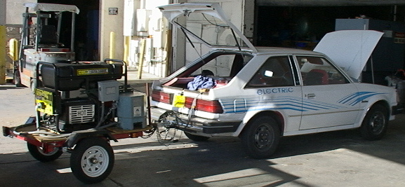
The
140 or so max DC amps from the generator trailer connects to the car
with standard electric forklift type battery connectors. The
collection of sensor and control wires have not yet been fitted with
connectors so are currently hardwired to the car (can't run around
without the generator trailer at this time).
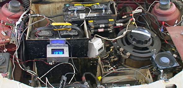
The image below
shows the view under the hood. The DPM showing 137
volts is
for monitoring the battery pack voltage on charging. The
white
box just to the right of it is the wall chargeing KWH meter.
The
large variac is used to adjust the charge current/charging voltage.
The muffin fan to the right and below the variac is for
cooling
the charger rectifier heatsink. There are 3 traction
batteries
and the auxillary battery up front.
This
is an experimental test bed setup. Most every thing as
subject to
change. I try to see that things are tidy enough so as not to
be
a problem but I don't want to go to the time/cost of making things
permanent when I know they are going to change.
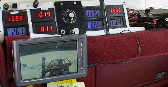
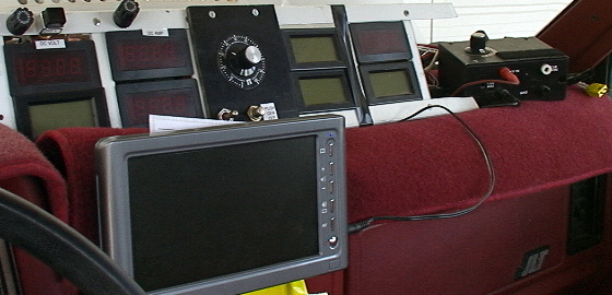
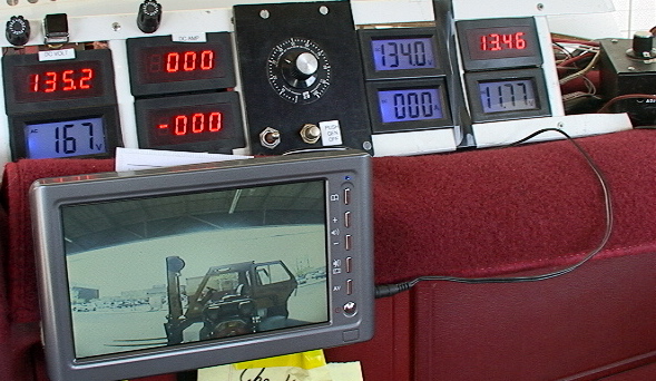
There
are currently 8 digital panel meters on the dash. In the
image
above, the generator is powered up and connected. In the
image
below, the generator is not connected, running at idle. The
square button just to the right of the left-most fuse. connects and
disconnects the generator. The upper left meter shows the DC voltage
just down stream from the generator rectifier. The LCD meter
below that shows the 240 volt AC output of the generator (the value
ranges from about 265 down to 210 depending on the load on the
generator). The meter showning 19 in the image above is the
120
volt current output from the generator. The meter reading 11
below it is the 240 volt side current (having this meter pair has been
important as we found it easy to get too much voltage on the
transformer which resulted in saturation and really poor efficiency.
The dial in the middle turns the small variac that runs to
the
generators voltage regulator that gives us the ability to control the
output voltage of the generator over a nominal range of values.
The toggle switch below it is the generator starter and the
button to the right of that is the generator kill switch. The
LCD
Above and to the right is the battery pack voltage. The meter below
that is the motor current draw (if it is smaller than the generator
current, then all traction current should be coming from the generator
and the battery should be getting charged (hardly ever happens).
The upper right meter is the individual battery
voltage--there is
a multi-position switch to the right on top a black box that allows
selection of any one of the 10 batteries--reading #10 in this case.
The last meter is the voltage of the auxillary battery.
(Note that we have not made any effort to calibrate any of
the
meters at this time.) We have a video backup camera in place
to
aid seeing what is behind as the generator blocks the view of the
rearview mirror.
DATA:
We
did a little battery testing last Friday. Unfortunately, I have
not figured out how to imbed a spreadsheet and chart in this HTML
document. If the link below does not work directly, you should be
able to paste the URL below it into your browser.
Battery Load Test
http://www.jetelectrica.org/battery%20curves%201.pdf
First
we took the auxillary battery out and stuck it on a battery load tester
we have. This battery is about 18 months old. It is the
same as the Costco batteries we are using in the main pack but about a
hear older. It gets charged from the main pack via a 3 amp laptop
AC adapter all the time with a maximum voltage of about 13.5 volts.
It has developed really serious internal resistance based on
these results. We tested as we took it out of the car, and then
after we charged it with a microprocessor controlled automotive
charger. There was hardly any difference. We only got about
140 amps out of it at 8 volts.
We took amperage and voltage
reading on the fly while driving home Friday afternoon. The
results are plotted in yellow. This was done within a couple
miles of having been charged out of the wall. We got to 300 amps
at 110 volts. This is contrasted to the two reading in yellow
that were taken in the morning shortly after charging. Here we
only got 200 amps at 105 volts. The only obious diffenence being
it was around 80 degrees F in the afternoon and 50 degrees in the
morning. (Also note that the testing was done with completely
different equipment.)
Followup will be to do the testing with more matched conditions/equipment.
BLOGGY TYPE
NOTES:
4/21/09
-Had the genset looked at by small motor shop--concluded gas splashing
from carb due to bouncy ride was causing overfueling.
-Genset side DC voltage meter misbehaved--showed a fixed 66.
Later went to normal operation with no known cause.
-Tech made a metal sun shade for the meters--the LCD's went black
Saturday sitting in the sun without enough ventilation.
-Genset
would not start on the trip home when the time came. Did not
stop
soon enough and get out to use the choke (no remote choke at this
point). Genset battery too low to start then genset when I
did
stop (was obvious we did not have enough battery to climb the hill to
home). Unfortuately, not carrying any jumper cables.
Took
out auxillary battery and used long battery hold down bolts to jump
from auxillary battery to genset battery to get it started.
Got
;in and discovered the genset voltage was outrageously high (300 plus
volts) and charging current was much higher than normal for no running
load. Genset tripped out within 15 to 20 seconds.
Discovered the genset voltage control variac setting had
gotten
changed when the sun shade was added. Could not get the
genset
voltage control to work for several minutes--then it came back. Spent
several minutes trying to relocate the previously used variac setting.
(Need to revisit the setting for minimum transformer loss
versus
the ability to run at higher charging voltage. Need to be
careful
not to zap the Curtis 1231 120 volt controller.)
-Rest of the drive home pretty much normal--battery more depleted than
normal.
4/22/09
Turned the key in the morning and heard the fans come on but no lights
on the display and not throttle response. Spent a good hour
trying to find the problem (yes, schematics would have been very
helpful). Finally gave up and wired a switched jumber from
the battery to the main battery pack solenoid so we could go.
On arrival at our first stop, discovered the key switch was
working again (it did not shut down when I turned my temporary jumper
switch off). Once I got to the shop, my tech noted he had
seen the same problem once and that it was the intlock switch in the
wall charging plug. Had one of the guys make me a jumper
cable long enough to reach from the auxillary battery to the genset
battery in case I had the dead battery problem again. Checked
the gensets 12 volt output--seems to be working but not very strongly.
4/23/09
Sure enough, the same thing this morning. Turned the key and
gauges did not come one. Took a number of attempts with the
wall charger plug interlock button to get the switch un-stuck.
Will need to get deeper into it for an actual fix.
4/24/09
Did initial battery discharge curve testing as noted above.
4/26/09
Started crunching some numbers. Updated this web page.
Found an error in the initial KWH per mile calculations (its
better than I first thought).
charles@cavlon.com